Overview
This page shows the collection of custom PCBs I've designed. All of the final boards were prototyped on a breadboard and/or protoboard before the final schematic was created and ordered.
Shown to the left is the finished H Bridge PCB I designed for basic motor control.
H Bridge
This was designed for a class project in Electronics and Controls. Starting with a breadboard prototype, the H-Bridge uses 2 N-channel MOSFETs, 2 P-channel MOSFETs, and 2 BJT transistors to allow a low voltage 3.3v signal from a microcontroller to control the motor direction. The final PCB was designed to connect to a motor via a screw terminal and accept power from either a barrel jack or another screw terminal.
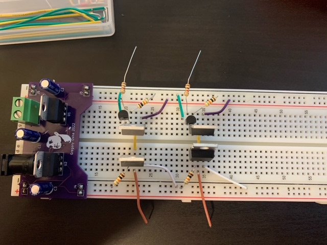
Breadboard Prototype
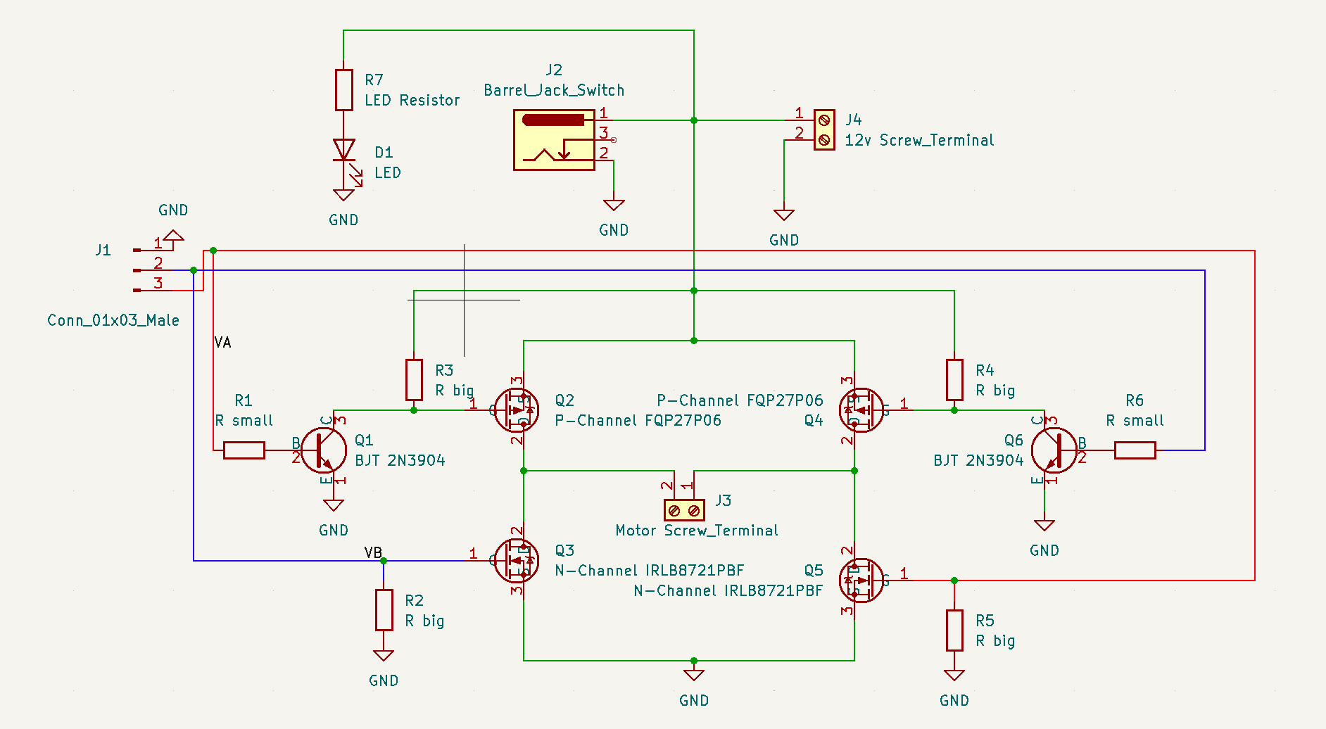
Schematic
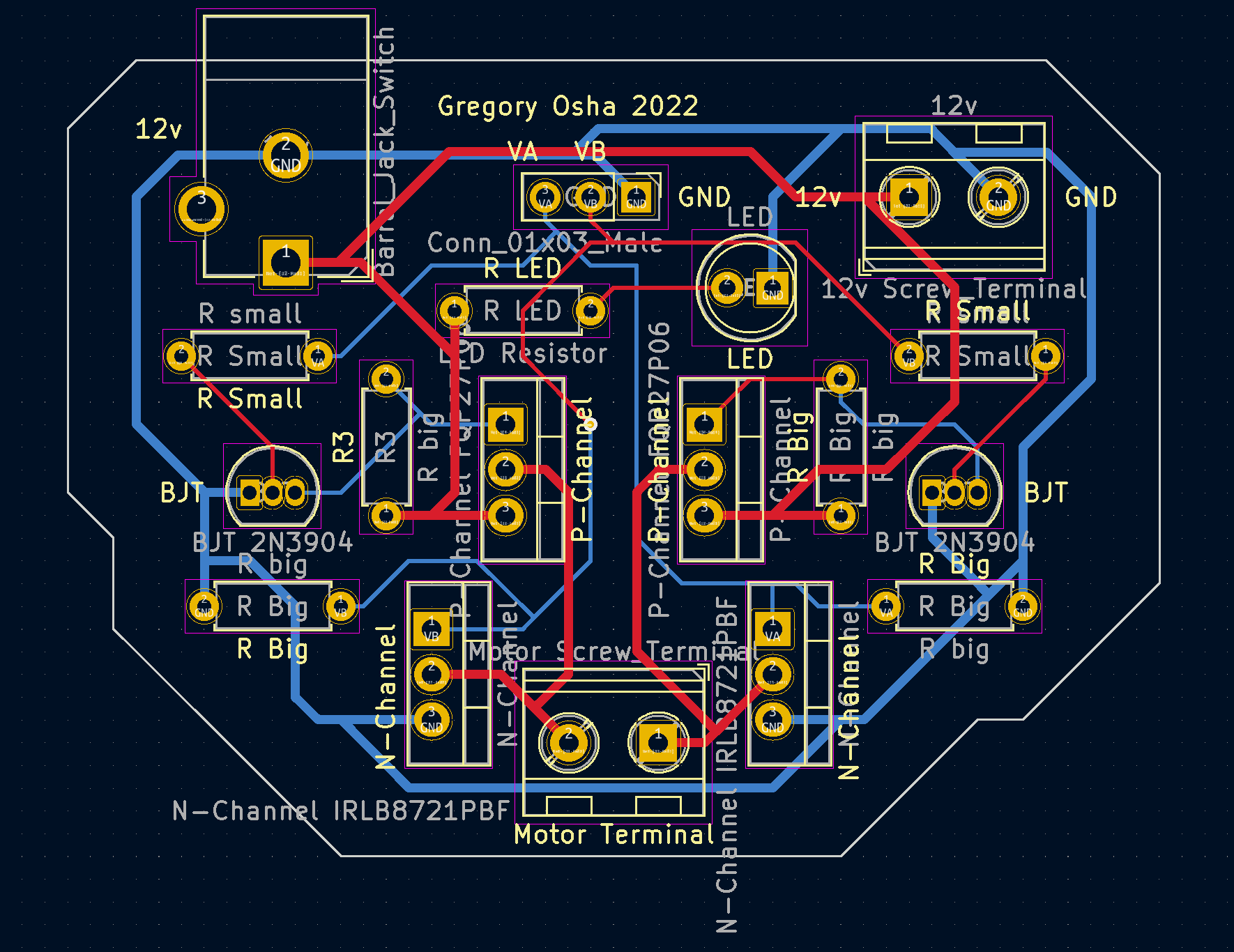
PCB
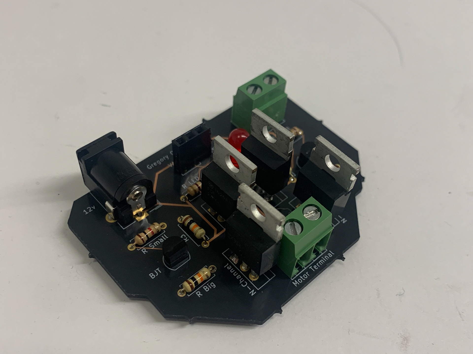
Soldered H Bridge
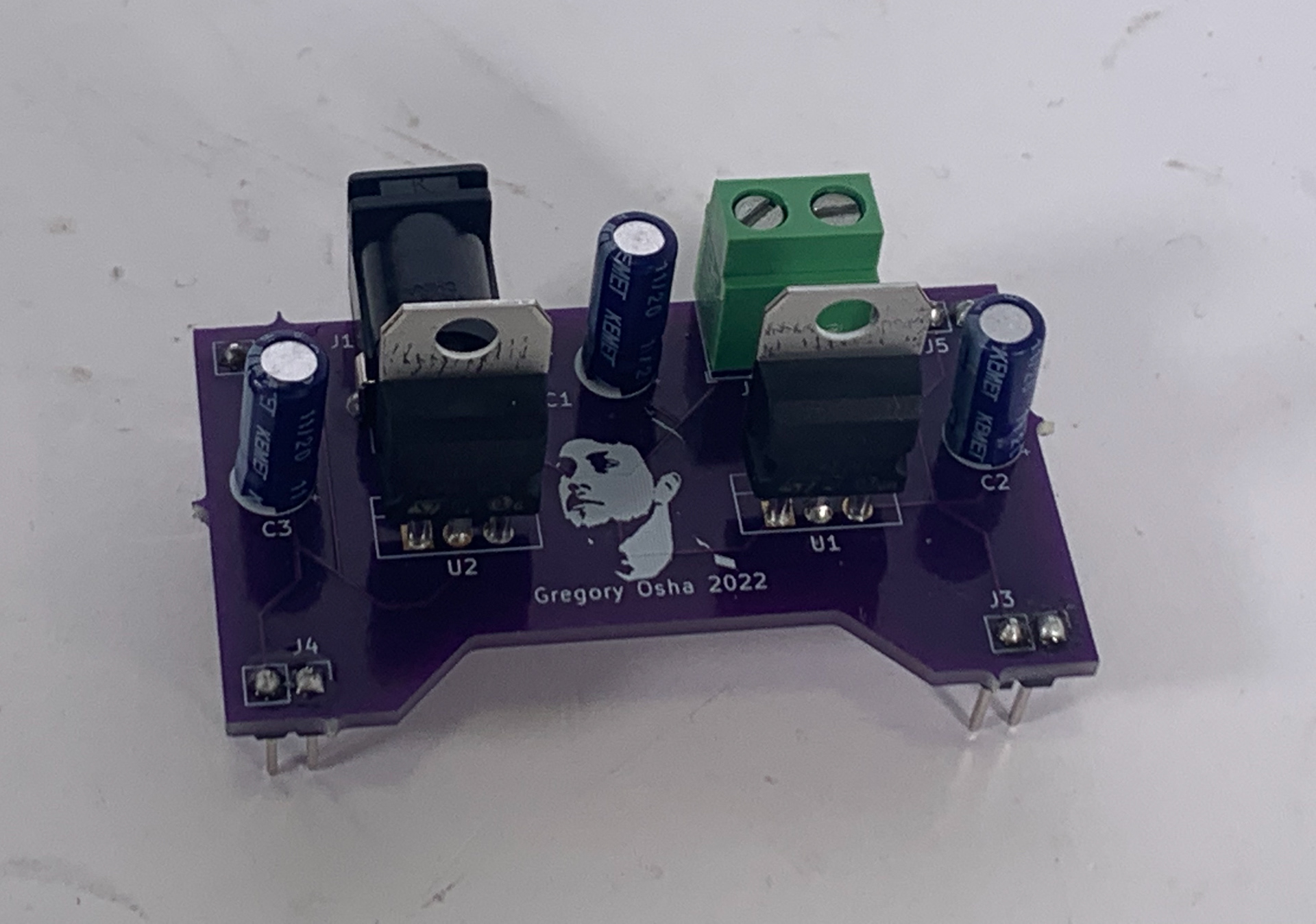
Power Supply
This project was designed to supply 5v and 3.3v to the power rails on a breadboard from a 12v barrel jack input. The design also makes use of capacitors to resist any voltage fluctuations from the power input. This was my first time designing a PCB from scratch, so it also involved learning KiCAD and moving from a breadboard prototype to a final PCB.
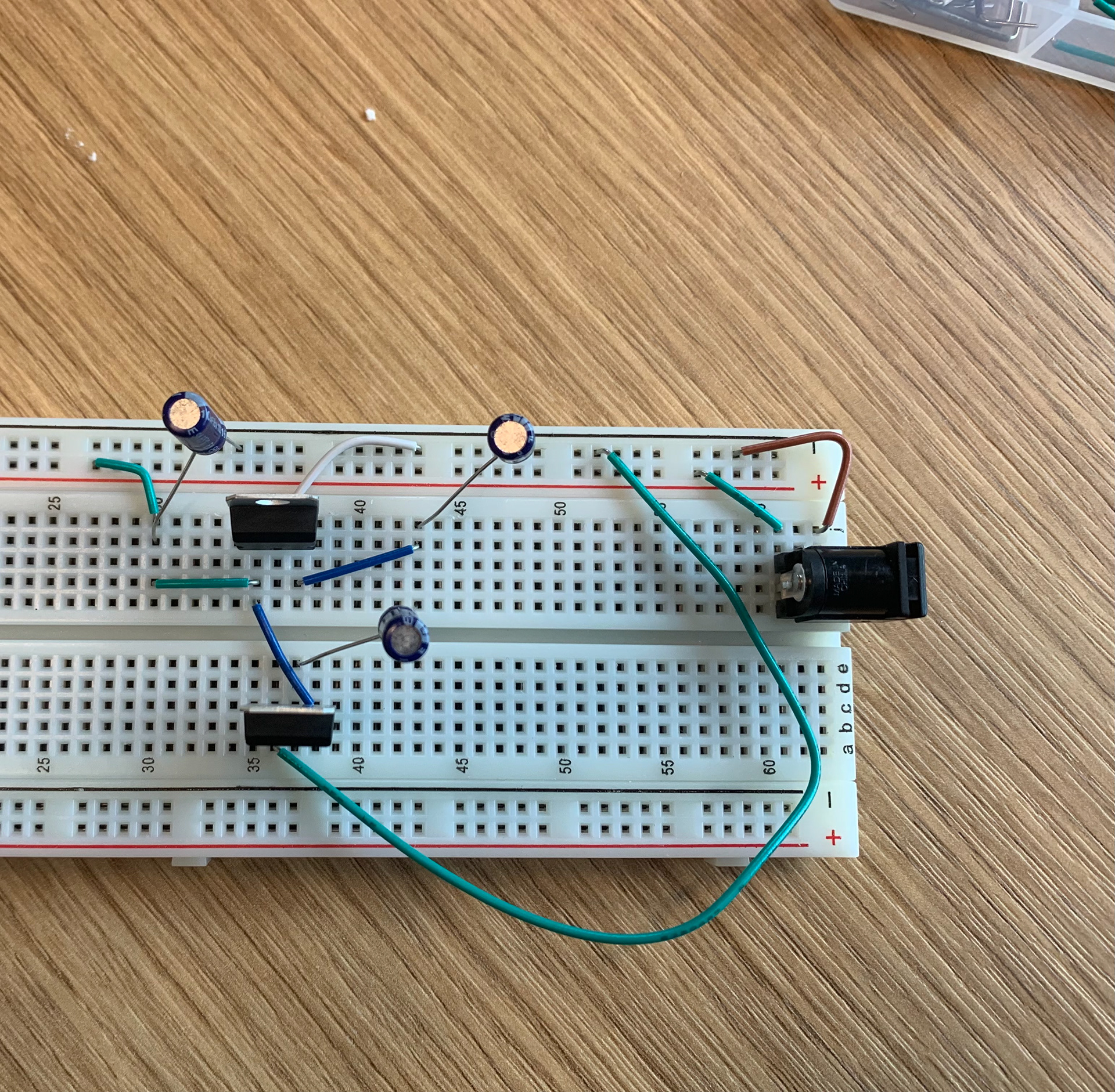
Breadboard Prototype
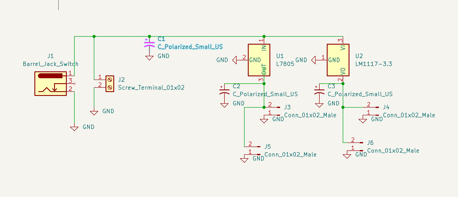
Schematic Layout
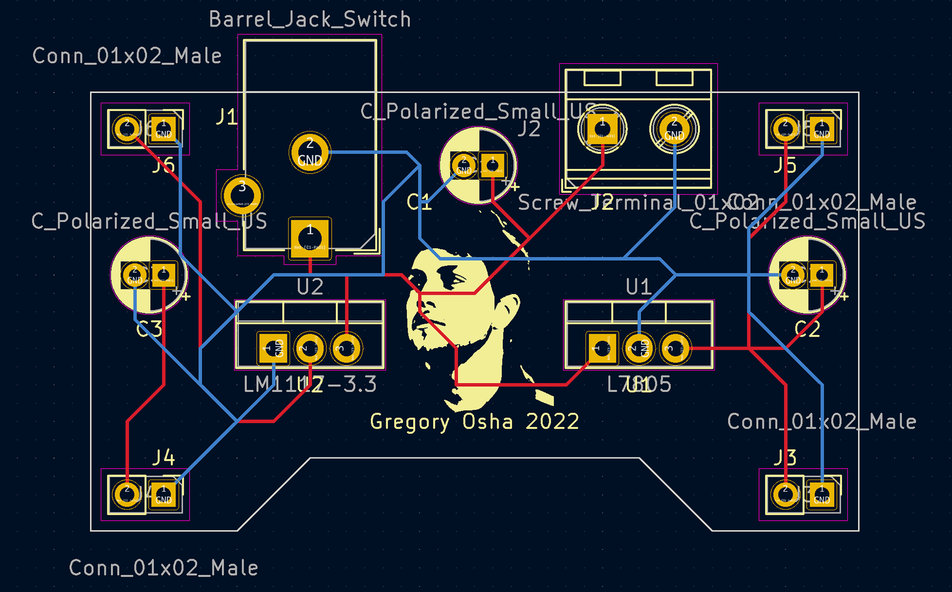
PCB Design
